PCB Design
SensEdu focuses on the design and development of a Printed Circuit Board (PCB) tailored for the Arduino GIGA R1. The objective is to create a versatile and efficient platform capable of accommodating a wide range of ultrasound applications, ensuring optimal performance and ease of integration.
Overview
This shield extends the Arduino Giga’s capabilities for ultrasound applications, including:
- 4-channel MEMS microphone array (Infineon IM73A135V01XTSA1) for signal acquisition.
- Ultrasound transmitters (Prowave 328ST160) for generating 32.8 kHz signals.
- Multi-voltage LDOs for stable digital power.
- DPS310 barometric sensor for environmental compensation.
- Flexible input/output routing via jumpers.
Software Used

The PCB for this project was designed using KiCad, an open-source software suite for electronic design automation (EDA). KiCad offers a comprehensive set of tools for schematic capture, PCB layout, and 3D visualization.
- Version: 7
- Features:
- Schematic Capture: Design complex circuit diagrams with ease.
- PCB Layout: Powerful tools for multilayer PCB design.
- 3D Viewer: Visualize your board in 3D to check component placement and fit.
Installation and Setup of KiCad
- Download KiCad:
- Visit the KiCad download page.
- Select your operating system (Windows, macOS, Linux) and download the installer.
- Install KiCad:
- Windows:
- Run the downloaded installer.
- Follow the on-screen instructions to complete the installation.
- Optionally, install additional libraries and templates.
- macOS:
- Open the downloaded
.dmgfile. - Drag the KiCad application to the Applications folder.
- Open the downloaded
- Linux:
- Follow the instructions on the KiCad download page for your specific Linux distribution.
- Windows:
- Initial Configuration:
- Launch KiCad.
- Go to
Preferences > Configure Pathsto set up the environment variables. - Add any custom libraries or footprints if needed.
- Open the
SensEduProject:- Download the
SensEduproject files from the repository. - Place the project files in a desired directory on your computer.
- Open KiCad and click on
File > Open Project. - Navigate to the directory where the
SensEduproject files are located and select the project file.kicad_pro
- Download the
KiCad Files
- Schematic: Download the PDF
PCB Layout
4-Layer Stackup
- Top Layer: Signal routing for components.
- Layer 2: Solid ground plane (noise reduction).
- Layer 3: Power planes (3.3V, 2.5V, 1.25V).
- Bottom Layer: Signal routing for for components.
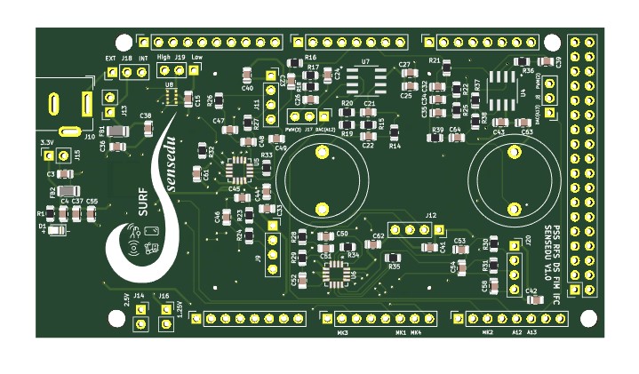
Front side
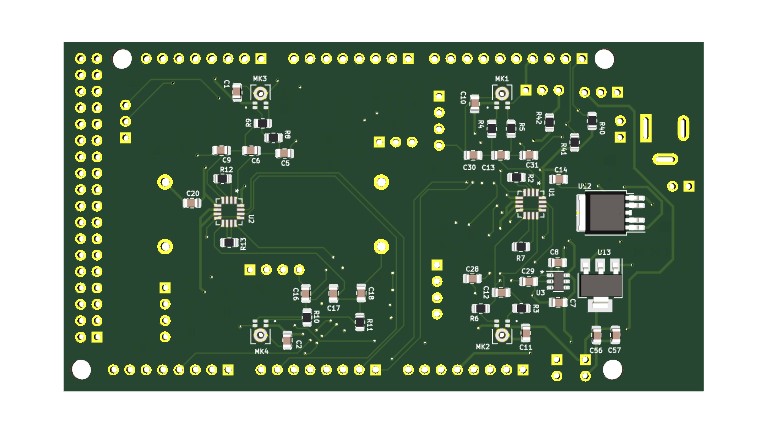
Back side
Hardware Design
Power Supply
Key Components:
- Primary LDO (Infineon TLS850C2TEV33ATMA1):
- Converts 5V (Arduino) or DC barrel jack (7–12V) to 3.3V for the shield.
- Selected for low noise (22 µV RMS) and high PSRR (70 dB) to stabilize analog circuits.
- Secondary LDOs:
- NCP1117-2.5_SOT223: Generates 2.5V for MEMS microphones.
- LT1790ACS6-1.25: Provides 1.25V reference for amplifier outputs.
Power Paths:
- Barrel Jack (J10) → Jumper J18 → TLS850 LDO → 3.3V rail.
- Arduino 5V → Jumper J18 → TLS850 LDO → 3.3V rail.
Indicators:
- Green LED lights when 3.3V is active.
Sensors
-
MEMS Microphones (Infineon IM73A135V01XTSA1)
The Infineon IM73A135V01XTSA1 is a high-performance MEMS Analog microphone designed for precise sound capture. It is particularly suitable for ultrasound applications due to its high Signal-to-Noise Ratio (SNR) and low Total Harmonic Distortion (THD).
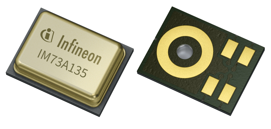
- Quantity: 4
- Key Features:
- SNR: 73 dB, which is excellent for capturing low-level ultrasound signals with high fidelity.
- Frequency Response: Wide and flat frequency response suitable for ultrasound frequencies.
- Sensitivity: -38 dBV/Pa, ensuring that even weak ultrasound signals can be detected.
- Low Power Consumption: Efficient power usage, critical for battery-operated or low-power applications.
- Power Supply:
- 2.5V supply from the NCP1117 LDO.
- Outputs Routed to Arduino ADC Pins:
- MK1 → A5
- MK2 → A10
- MK3 → A1
- MK4 → A6
-
Barometric Pressure Sensor (Infineon DPS310)
The DPS310 is a high-precision barometric pressure sensor designed by Infineon. It measures both pressure and temperature, providing essential environmental data that can be used to compensate for variations in ultrasound propagation due to changes in atmospheric conditions.
- Interface: I2C (SCL1/SDA1)
- Key Features:
- Pressure Range: 300 to 1200 hPa, suitable for most environmental conditions.
- Temperature Range: -40 to 85°C, allowing for robust operation in various environments.
- High Accuracy: Pressure accuracy of ±1 hPa and temperature accuracy of ±0.5°C, ensuring precise environmental compensation.
- Low Power Consumption: Ideal for continuous monitoring without significant power drain.
- Usage:
- The DPS310 is used to measure atmospheric pressure and temperature, which can then be used to adjust the ultrasound measurements for more accurate distance and velocity calculations.
Amplifiers
-
Instrumentation Amplifier (AD8426ACPZ-R7):
The AD8426ACPZ-R7 is a high-performance instrumentation amplifier from Analog Devices. It is designed for accurate, low-noise amplification of small differential signals, making it ideal for amplifying the weak signals from the MEMS microphones in ultrasound applications.
- Key Features:
- Low Noise: 1 nV/√Hz noise density, ensuring minimal introduction of noise into the signal.
- High Common-Mode Rejection Ratio (CMRR): Ensures that noise from the power supply or other sources is minimized.
- Single-Supply Operation: 3.3V supply voltage, compatible with the overall system design.
- Configurable Gain: Gain can be set using external resistors, with a typical configuration providing a gain of 50 (using a 1kΩ resistor).
- Usage in Design:
- Microphone Signal Amplification: The AD8426 amplifiers are used to boost the low-level signals from the MEMS microphones (IM73A135V01XTSA1) to levels suitable for digital processing.
- Configuration: 4x AD8426 amplifiers provide four channels of amplification, each with a gain of 50. In which 2 are for Infineon IM73A135V01XTSA1 microphones and 2 for external sources.
- Apmlifier for external signals: J9/J11/J12/J20: 4-pin headers for connecting external microphones or other signal sources.
- Pin 1: 2.5V (mic supply)
- Pin 2: Amplifier input -
- Pin 3: Amplifier input +
- Pin 4: GND
Ultrasound Transmitters
-
Speakers (Prowave 328ST160):
The Prowave 328ST160 is an ultrasound speaker designed specifically for emitting high-frequency sound waves. With a resonance frequency of 32.8 kHz, it is ideal for generating ultrasound signals that can be used in various applications such as distance measurement and object detection.
- Key Features:
- Resonance Frequency: 32.8 kHz, which is optimal for many ultrasound applications.
- High Sound Pressure Level (SPL): Ensures strong and consistent ultrasound signal transmission.
- Directional Beam Pattern: Focuses the ultrasound waves, improving accuracy in detecting reflections from objects.
- Durability: Designed to withstand environmental factors, making it suitable for both indoor and outdoor applications.
- Integration in Design:
- Driving Circuit: The ultrasound speakers are driven by the ADA4891-1ARZ-R7 operational amplifier, which provides the necessary gain and power to achieve optimal performance.
- 2x Speakers (LS1&LS2)
- Signal Input Options:
- Analog Waveforms: Provided through Arduino DAC pins (A12 and A13).
- PWM Signals: Filtered through an RC network (4.7kΩ resistor and 1nF capacitor → cutoff ~34 kHz) to achieve a smooth signal, selectable via jumpers J8 and J17.
- Power Supply: Operates with a single 3.3V supply, ensuring compatibility with the rest of the system.
-
Operational Amplifier (ADA4891-1ARZ-R7):
The ADA4891-1ARZ-R7 is a high-speed, low-noise operational amplifier from Analog Devices. It is designed for applications requiring fast and precise signal amplification, making it suitable for driving the ultrasound transmitters (Prowave 328ST160). - Key Features:
- High Slew Rate: Ensures rapid response to input signal changes, critical for generating clean ultrasound signals.
- Low Noise: Low input noise density, providing a clean amplification of the input signal.
- Single-Supply Operation: 3.3V supply voltage, compatible with the overall system design.
- Configurable Gain: Gain can be set using external feedback resistors, with the current configuration providing a gain of 4 (using a 3kΩ feedback resistor and a 1kΩ resistor to ground).
- Usage in Design:
- Driving Ultrasound Transmitters: The ADA4891 amplifiers are used to drive the Prowave 328ST160 speakers, providing the necessary power and precision to generate effective ultrasound signals.
- Integration: Operates with a single 3.3V supply, ensuring compatibility with the rest of the system.
Design Choices
- Ground plane isolates sensitive analog paths.
- Short traces for amplifier inputs to minimize noise.
Connections & Pinouts
Key Headers/Jumpers:
| Component | Function |
|---|---|
| J18 | Selects power source (Arduino 5V or barrel jack). |
| J8/J17 | Route PWM/DAC signals to transmitters. |
| J13 | Barrel jack input (7–12V). |
| J15/J14/J16 | Test points for 3.3V, 2.5V, 1.25V. |