PWM Peripheral
Pulse-Width Modulation (PWM) is a digital signal with a varying duty cycle, used to control the average power delivered to a system. It is commonly applied in motor control, LED dimming, switching power supplies, audio signal generation, and many other fields.
Errors
The main PWM error code prefix is 0x50xx. Find the way to display errors in your Arduino sketch here.
An overview of possible errors for PWM signals:
0x5000: No Errors0x5001: Invalid Arduino pin (onlyD4,D37,D48, andD71are supported)0x5002: Unexpected PWM frequency. Allowed range is \(1\text{Hz} - 60\text{MHz}\)0x5003: Unexpected PWM duty cycle. Allowed range is \(0\% - 100\%\)
Functions
SensEdu_PWM_Init
Initializes PWM with the selected frequency and duty cycle.
void SensEdu_PWM_Init(uint8_t arduino_pin_idx, uint32_t freq, uint8_t duty_cycle);
Parameters
arduino_pin_idx: Arduino Pin (D4,D37,D48, orD71)freq: PWM frequency (\(1\text{Hz} - 60\text{MHz}\))duty_cycle: PWM duty cycle (\(0\% - 100\%\))
Notes
- Configures the associated timer and GPIO.
- With multiple PWM initializations are called, the timer is configured only once internally. Be cautious if you expect the timer to be in a reset state.
PWM supports only a single frequency across all channels.
If different frequencies are requested, the last one set will apply globally. Duty cycle, however, remains independent per channel.
SensEdu_PWM_Init(D4, 100, 25);
SensEdu_PWM_Init(D37, 200, 50);
SensEdu_PWM_Init(D48, 300, 75);
SensEdu_PWM_Init(D71, 400, 100);
Resulting settings:
| Arduino Pin | Frequency | Duty Cycle |
|---|---|---|
| D4 | 400Hz | 25% |
| D37 | 400Hz | 50% |
| D48 | 400Hz | 75% |
| D71 | 400Hz | 100% |
SensEdu_PWM_Start
Starts PWM generation.
void SensEdu_PWM_Start(void);
Notes
- Internally enables the timer.
- Forces an update event before enabling the timer, ensuring the latest configuration is applied. Refer to configuration section for details.
SensEdu_PWM_Stop
Stops PWM generation.
void SensEdu_PWM_Stop(void);
Notes
- Internally disables the timer.
- Forces an update event after disabling the timer, resetting outputs to LOW by default. Refer to configuration section for details.
SensEdu_PWM_SetFrequency
Sets a new frequency for the PWM signal.
void SensEdu_PWM_SetFrequency(uint32_t freq);
Parameters
freq: PWM frequency (\(1\text{Hz} - 60\text{MHz}\))
Notes
- Updates
ARRandPSCregisters to adjust frequency. CCRxregisters on all 4 channels are scaled accordingly to preserve their duty cycle ratios.
SensEdu_PWM_SetDutyCycle
Sets a new duty cycle for a given PWM channel.
void SensEdu_PWM_SetDutyCycle(uint8_t arduino_pin_idx, uint8_t duty_cycle);
Parameters
arduino_pin_idx: Arduino Pin (D4,D37,D48orD71)duty_cycle: PWM duty cycle (\(0\% - 100\%\))
Notes
- Duty cycles are internally inverted, so the library computes \((100 - \text{duty_cycle})\) to achieve the intended result.
Examples
Generate_PWM
Demonstrates how to generate continuous PWM signal on x4 outputs with different duty cycles.
- Include SensEdu library
- Declare PWM pins
- Initialize each PWM pin using
SensEdu_PWM_Init() - Start PWM with
SensEdu_PWM_Start()
#include "SensEdu.h"

uint8_t pwm_chs[4] = {D4, D37, D48, D71};

void setup() {
    SensEdu_PWM_Init(pwm_chs[0], 100000, 25);
    SensEdu_PWM_Init(pwm_chs[1], 100000, 50);
    SensEdu_PWM_Init(pwm_chs[2], 100000, 75);
    SensEdu_PWM_Init(pwm_chs[3], 100000, 100);
    SensEdu_PWM_Start();
}

void loop() {
    // do nothing
}
Below is the figure of the resulting PWM waveforms for pins D4 (black), and D37 (blue).

Generate_PWM_Freq_Sweep
This example shows how to generate a sequence of PWM signals with gradually increasing frequencies on one output pin.
- Follow the same basic configuration as in the
Generate_PWM - Add a custom delay timer as described in
Blink_Delay. This delay is used to control the duration of each individual frequency - Configure the parameters:
- Starting frequency (
fstart) - Ending frequency (
fend) - Number of steps (
steps) - Duration of each frequency (
step_dur_ms)
- Starting frequency (
- Calculate the frequency increment based on the range
fstart - fend, andsteps - Trigger the sequence using an external input, such as a button press or serial input
- Iterate through the frequency steps:
- Set the current frequency with
SensEdu_PWM_SetFrequency() - Start the PWM with
SensEdu_PWM_Start() - Wait for the desired duration using custom delay
SensEdu_TIMER_Delay_us() - Stop the PWM with
SensEdu_PWM_Stop()
- Set the current frequency with
uint32_t freq_increment = (fend-fstart)/(steps-1);
for (uint32_t i = 0; i < steps; i++) {
    uint32_t freq = fstart + i * freq_increment;
    if (i == steps - 1) {
        freq = fend;
    }
    SensEdu_PWM_SetFrequency(freq);
    SensEdu_PWM_Start();
    SensEdu_TIMER_Delay_us(1000 * step_dur);
    SensEdu_PWM_Stop();
}
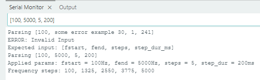
To make the example more flexible, it includes a Serial input parser, allowing for dynamic inputs in the form [fstart, fend, steps, step_dur_ms], avoiding the need to recompile hardcoded values every time you want to test a different configuration.
Below is an example of the resulting waveform with an input [100, 5000, 5, 200]. On the oscilloscope there are 5 distinct frequency gradients, with each frequency held for \(200\text{ms}\).

Notes
- Stopping and restarting the PWM helps with precise timing on selected
step_dur_ms. However, if small variations in timing are acceptable, you can simplify the implementation by skipping the stop/restart steps. You can use justSensEdu_PWM_SetFrequency()and nothing more. The new frequency is updated naturally on the next update event. This approach results in cleaner transitions between each frequency.
uint32_t freq_increment = (fend-fstart)/(steps-1);
for (uint32_t i = 0; i < steps; i++) {
    uint32_t freq = fstart + i * freq_increment;
    if (i == steps - 1) {
        freq = fend;
    }
    SensEdu_PWM_SetFrequency(freq);
    SensEdu_TIMER_Delay_us(1000 * step_dur);
}
Developer Notes
Theory of Operation
PWM generation relies on the timer counting up to the ARR register, which defines the signal’s period. At a specific fraction of the ARR defined in the CCR (Capture/Compare Register), the signal toggles, creating the desired duty cycle. By adjusting the CCR value, you can control the proportion of the high state in the signal, thus setting the PWM duty cycle.
If you are not familiar with timer frequency calculations, refer to the corresponding section on the Timers page.
For example, a \(50\%\) duty cycle can be achieved using the following configuration. Assume the timer parameters \(TIM_{CLK} = 240\text{MHz}\), \(PSC = 23\), and \(ARR = 9\). The resulting frequency is calculated as:
\[f_{PWM} = \frac{240 * 10^6}{23 + 1} * \frac{1}{9 + 1} = 1\text{MHz}\]Selected \(CCR = (ARR + 1) / 2 = 5\) results in exactly \(50\%\) duty cycle.
The library provides the flexibility to use one of x4 CCRx registers (CCR1, CCR2, CCR3, or CCR4), allowing for PWM outputs with different duty cycles on the same timer.
For more information, the PWM Tutorial on DEEPBLUEMBEDDED is highly recommended.
Configuration
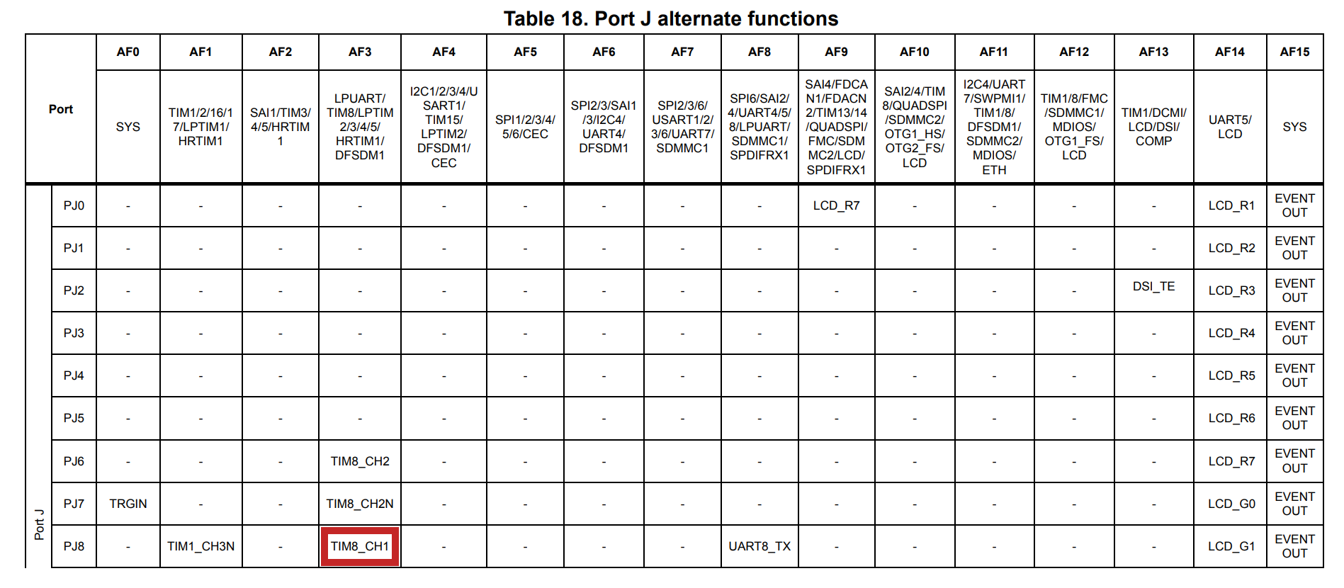
PWM is implemented using the timer TIM8. Refer to the Arduino GIGA R1 Schematics to locate the pins with TIM8 output.
| Arduino Pin | STM Pin | Timer Channel |
|---|---|---|
| D4 | PJ8 | TIM8_CH1 |
| D37 | PJ6 | TIM8_CH2 |
| D48 | PK0 | TIM8_CH3 |
| D71 | PI2 | TIM8_CH4 |
Find all configuration details for TIM8 in Chapter 40.3 TIM1/TIM8 of STM32H747 Reference Manual.
In this setup, TIM8 is configured in the upcounting mode and operates in PWM Mode 2, which means the channel remains inactive as long as TIM8_CNT < TIM8_CCRx. It makes the PWM active-high.
Additionally, preloading is enabled for ARR, PSC, and CCRx values. Preloading means these values are stored first in shadow registers and only transferred to the actual registers during an “update event” (UEV). This event occurs naturally when the counter reaches the overflow, but could also be generated by software. Preloading ensures the precise synchronous application of the settings, instead of occurring at some random uncontrollable time, leading to indeterminate latency and unpredictable behavior.
Since preloading is enabled, the library generates the update event before starting the PWM to ensure the most recent settings are applied.
After configuring the timer, the next step is to route the timer’s output signal to the appropriate I/O pin. Detailed instructions could be found in Chapter 12 GPIO of STM32H747 Reference Manual.
GPIO is configured for highest speed, and with no pull-up or pull-down resistors. To output the timer signal via a GPIO pin, the alternate function mode must be selected. There are multiple available functions for each pin, the proper index for TIM8 could be found by consulting the Tables 9 to 19 in Chapter 5 of STM32H747 Datasheet. In this case, for TIM8_CH1-4 the alternate function index is 3, therefore GPIO is configured with AF3.