Other Examples
These examples illustrate more complex, yet fundamental, applications of multiple peripherals.
Basic Ultrasound Examples
These examples demonstrate how to transmit a 32kHz ultrasonic wave at a constant sampling rate. The reflected wave is then captured and sent to a PC via Serial or WiFi communication. Using MATLAB, you can visualize and potentially process the wave. By placing an object on top of the SensEdu, you can observe wave reflections.
To run these examples, you need to install MATLAB.
Basic_UltraSound
Utilizes only one microphone.
Step 1 : Include SensEdu library.
#include "SensEdu.h"
Step 2 : Create a lookup table (LUT) that contains a sine wave.
const uint16_t dac_cycle_num = 10; // sine cycles

const uint16_t sine_lut_size = 64; // sine wave size
const SENSEDU_DAC_BUFFER(sine_lut, sine_lut_size) = {
    0x0000,0x000a,0x0027,0x0058,0x009c,0x00f2,0x0159,0x01d1,
    0x0258,0x02ed,0x038e,0x043a,0x04f0,0x05ad,0x0670,0x0737,
    0x0800,0x08c8,0x098f,0x0a52,0x0b0f,0x0bc5,0x0c71,0x0d12,
    0x0da7,0x0e2e,0x0ea6,0x0f0d,0x0f63,0x0fa7,0x0fd8,0x0ff5,
    0x0fff,0x0ff5,0x0fd8,0x0fa7,0x0f63,0x0f0d,0x0ea6,0x0e2e,
    0x0da7,0x0d12,0x0c71,0x0bc5,0x0b0f,0x0a52,0x098f,0x08c8,
    0x0800,0x0737,0x0670,0x05ad,0x04f0,0x043a,0x038e,0x02ed,
    0x0258,0x01d1,0x0159,0x00f2,0x009c,0x0058,0x0027,0x000a
};
Step 3 : Initialize the SensEdu_DAC_Settings struct with DAC parameters. Refer to DAC page for details.
#define DAC_SINE_FREQ       32000                           // 32kHz
#define DAC_SAMPLE_RATE     DAC_SINE_FREQ * sine_lut_size   // 64 samples per one sine cycle

DAC_Channel* dac_ch = DAC_CH1;
SensEdu_DAC_Settings dac_settings = {
    .dac_channel = dac_ch,
    .sampling_freq = DAC_SAMPLE_RATE,
    .mem_address = (uint16_t*)sine_lut,
    .mem_size = sine_lut_size,
    .wave_mode = SENSEDU_DAC_MODE_BURST_WAVE,
    .burst_num = dac_cycle_num
};
Step 4 : Initialize the SensEdu_ADC_Settings struct with ADC parameters. Refer to ADC page for details. Array for ADC must have the proper size and be cache aligned, you can read more about this here.
const uint16_t mic_data_size = 16*128; // must be multiple of 16 for 16bit
__attribute__((aligned(__SCB_DCACHE_LINE_SIZE))) uint16_t mic_data[mic_data_size];

ADC_TypeDef* adc = ADC1;
const uint8_t mic_num = 1;
uint8_t mic_pins[mic_num] = {A1};
SensEdu_ADC_Settings adc_settings = {
    .adc = adc,
    .pins = mic_pins,
    .pin_num = mic_num,

    .conv_mode = SENSEDU_ADC_MODE_CONT_TIM_TRIGGERED,
    .sampling_freq = 250000,

    .dma_mode = SENSEDU_ADC_DMA_CONNECT,
    .mem_address = (uint16_t*)mic_data,
    .mem_size = mic_data_size
};
Step 5 : Initialize DAC and ADC with created structs. Enable Serial for communication with PC.
void setup() {
    Serial.begin(115200);

    SensEdu_DAC_Init(&dac_settings);
    SensEdu_ADC_Init(&adc_settings);
    SensEdu_ADC_Enable(adc);
}
Step 6 : Create a buffer that waits for a command (e.g., symbol “t”) from MATLAB. To simplify synchronization between Arduino and MATLAB, it is easier to trigger the UltraSound via Serial.
void loop() {

    static char serial_buf = 0;
    while (1) {
        while (Serial.available() == 0); // Wait for a symbol
        serial_buf = Serial.read();

        if (serial_buf == 't') {
            // expected 't' symbol (trigger)
            break;
        }
    }
Step 7 : Start the transmission of the sine wave and wait until it is completed.
    SensEdu_DAC_Enable(dac_ch);
    while(!SensEdu_DAC_GetBurstCompleteFlag(dac_ch));
    SensEdu_DAC_ClearBurstCompleteFlag(dac_ch);
Step 8 : Start the data acquisition and wait until it is completed.
    while(!SensEdu_ADC_GetTransferStatus(adc));
    SensEdu_ADC_ClearTransferStatus(adc);
Step 9 : Send the received wave data to MATLAB via Serial.
    serial_send_array((const uint8_t *) & mic_data, mic_data_size * 2);
} // close void loop()
// send serial data in 32 byte chunks
void serial_send_array(const uint8_t* data, size_t size) {
    const size_t chunk_size = 32;
	for (uint32_t i = 0; i < size/chunk_size; i++) {
		Serial.write(data + chunk_size * i, chunk_size);
	}
}
Step 10 : Open matlab\Basic_UltraSound_ReadData.m. Specify Serial parameters and start connection with Arduino.
%% Settings
ARDUINO_PORT = 'COM4'; % match to Arduino COM
ARDUINO_BAUDRATE = 115200; % match to baudrate in `Serial.begin`
ITERATIONS = 10000; % script stops after this number of measurements
DATA_LENGTH = 16*128; % ensure this value matches `mic_data_size` in firmware

%% Arduino Setup
arduino = serialport(ARDUINO_PORT, ARDUINO_BAUDRATE);
Step 11 : Write a function in MATLAB to receive the data from Arduino. The function should handle 16-bit samples sent in bytes, so each sample consisting of 2 bytes. In the firmware, data is sent in 32-byte chunks, and the MATLAB function should match this to avoid synchronization issues.
function data = read_data(arduino, data_length)
    total_byte_length = data_length * 2; % 2 bytes per sample
    serial_rx_data = zeros(1, total_byte_length);

    for i = 1:(total_byte_length/32) % 32 bytes chunk size
        serial_rx_data((32*i - 31):(32*i)) = read(arduino, 32, 'uint8');
    end

    data = double(typecast(uint8(serial_rx_data), 'uint16'));
end
Step 12 : Create the main loop in MATLAB to send a trigger symbol “t” to Arduino, read the data, and plot it.
%% Readings Loop
data = zeros(1,ITERATIONS);

for it = 1:ITERATIONS
    write(arduino, 't', "char"); % trigger arduino measurement
    data = read_data(arduino, DATA_LENGTH);
    plot(data);
end

% set COM port back free
arduino = [];
Results : Below you can find two GIFs showing the measurement results.
First figure shows measurements taken without any object in sight. You can observe some signal at the beginning, which corresponds to the sound coupling from the speaker to the microphones.
Second figure shows measurements with a flat object placed near the board. Here, you can observe the wave reflection from the object.
Basic_UltraSound_4CH
Utilizes all four microphones.
Steps are the same as for Basic_UltraSound. The only difference is in ADC configuration and the method of receiving data. For a setup with four microphones, we could use two ADCs in 2-Channel mode.
const uint16_t mic_data_size = 16*128*2;
__attribute__((aligned(__SCB_DCACHE_LINE_SIZE))) uint16_t mic12_data[mic_data_size];
__attribute__((aligned(__SCB_DCACHE_LINE_SIZE))) uint16_t mic34_data[mic_data_size];


ADC_TypeDef* adc1 = ADC1;
ADC_TypeDef* adc2 = ADC2;
const uint8_t mic_num = 2;
uint8_t mic12_pins[mic_num] = {A5, A4};
uint8_t mic34_pins[mic_num] = {A1, A6};

SensEdu_ADC_Settings adc1_settings = {
    .adc = adc1,
    .pins = mic12_pins,
    .pin_num = mic_num,

    .conv_mode = SENSEDU_ADC_MODE_CONT_TIM_TRIGGERED,
    .sampling_freq = 250000,

    .dma_mode = SENSEDU_ADC_DMA_CONNECT,
    .mem_address = (uint16_t*)mic12_data,
    .mem_size = mic_data_size
};

SensEdu_ADC_Settings adc2_settings = {
    .adc = adc2,
    .pins = mic34_pins,
    .pin_num = mic_num,

    .conv_mode = SENSEDU_ADC_MODE_CONT_TIM_TRIGGERED,
    .sampling_freq = 250000,

    .dma_mode = SENSEDU_ADC_DMA_CONNECT,
    .mem_address = (uint16_t*)mic34_data,
    .mem_size = mic_data_size
};
For each ADC interaction, call both ADC1 and ADC2 (see example below). If you use the A9 pin for older board revisions, don’t forget to call SensEdu_ADC_ShortA4toA9, which is explained here.
SensEdu_ADC_ShortA4toA9();
SensEdu_ADC_Init(&adc1_settings);
SensEdu_ADC_Init(&adc2_settings);
SensEdu_ADC_Enable(adc1);
SensEdu_ADC_Enable(adc2);
In MATLAB, the difference is how you interpret the data. Since you use ADC in multichannel mode, the data is organized in series with CH1 sample following CH2 sample and then repeating for the whole dataset (CH1 → CH2 → CH1 → CH2 → CH1 → …). Change the receiving function to correctly interpret this data.
function [data_mic1, data_mic2] = read_2mic_data(arduino, data_length)
    total_byte_length = data_length * 2; % 2 bytes per sample
    serial_rx_data = zeros(1, total_byte_length);

    for i = 1:(total_byte_length/32) % 32 byte chunk size
        serial_rx_data((32*i - 31):(32*i)) = read(arduino, 32, 'uint8');
    end

    data = double(typecast(uint8(serial_rx_data), 'uint16'));

    data_mic1 = zeros(1, floor(length(data)/2));
    data_mic2 = zeros(1, floor(length(data)/2));
    ind = 1;
    for i = 1:2:length(data)
        data_mic1(ind) = data(i);
        data_mic2(ind) = data(i+1);
        ind = ind+1;
    end
end

% You can change `ind` to `i - (i-1)/2` to avoid additional variable.
Use read_2mic_data function twice to capture ultrasound data from all four microphones and plot it.
[data_mic1, data_mic2] = read_2mic_data(arduino, DATA_LENGTH);
[data_mic3, data_mic4] = read_2mic_data(arduino, DATA_LENGTH);
Results : Below you can find two GIFs showing the measurement results.
First figure shows measurements taken without any object in sight. You can observe some signal at the beginning, which corresponds to the sound coupling from the speaker to the microphones.
Second figure shows measurements with a flat object placed near the board. Here, you can observe the wave reflections from the object.
Basic_UltraSound_WiFi
Utilizes only one microphone. The example is similar to Basic_UltraSound, but uses WiFi as communication medium instead of Serial.
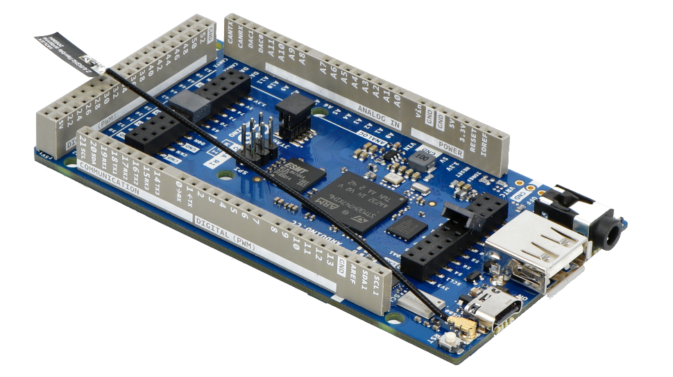
Step 0 : Connect an antenna to the Arduino GIGA R1 (provided in the bundle)
Step 1 : Include SensEdu and WiFi libraries.
#include "SensEdu.h"
#include <WiFi.h>
Step 2 : Create a lookup table (LUT) that contains a sine wave.
const uint16_t dac_cycle_num = 10; // sine cycles

const uint16_t sine_lut_size = 64; // sine wave size
const SENSEDU_DAC_BUFFER(sine_lut, sine_lut_size) = {
    0x0000,0x000a,0x0027,0x0058,0x009c,0x00f2,0x0159,0x01d1,
    0x0258,0x02ed,0x038e,0x043a,0x04f0,0x05ad,0x0670,0x0737,
    0x0800,0x08c8,0x098f,0x0a52,0x0b0f,0x0bc5,0x0c71,0x0d12,
    0x0da7,0x0e2e,0x0ea6,0x0f0d,0x0f63,0x0fa7,0x0fd8,0x0ff5,
    0x0fff,0x0ff5,0x0fd8,0x0fa7,0x0f63,0x0f0d,0x0ea6,0x0e2e,
    0x0da7,0x0d12,0x0c71,0x0bc5,0x0b0f,0x0a52,0x098f,0x08c8,
    0x0800,0x0737,0x0670,0x05ad,0x04f0,0x043a,0x038e,0x02ed,
    0x0258,0x01d1,0x0159,0x00f2,0x009c,0x0058,0x0027,0x000a
};
Step 3 : Initialize the SensEdu_DAC_Settings struct with DAC parameters. Refer to DAC page for details.
#define DAC_SINE_FREQ       32000                           // 32kHz
#define DAC_SAMPLE_RATE     DAC_SINE_FREQ * sine_lut_size   // 64 samples per one sine cycle

DAC_Channel* dac_ch = DAC_CH1;
SensEdu_DAC_Settings dac_settings = {
    .dac_channel = dac_ch,
    .sampling_freq = DAC_SAMPLE_RATE,
    .mem_address = (uint16_t*)sine_lut,
    .mem_size = sine_lut_size,
    .wave_mode = SENSEDU_DAC_MODE_BURST_WAVE,
    .burst_num = dac_cycle_num
};
Step 4 : Initialize the SensEdu_ADC_Settings struct with ADC parameters. Refer to ADC page for details. Array for ADC must have the proper size and be cache aligned, you can read more about this here.
const uint16_t mic_data_size = 16*128; // must be multiple of 16 for 16bit
__attribute__((aligned(__SCB_DCACHE_LINE_SIZE))) uint16_t mic_data[mic_data_size];

ADC_TypeDef* adc = ADC1;
const uint8_t mic_num = 1;
uint8_t mic_pins[mic_num] = {A1};
SensEdu_ADC_Settings adc_settings = {
    .adc = adc,
    .pins = mic_pins,
    .pin_num = mic_num,

    .conv_mode = SENSEDU_ADC_MODE_CONT_TIM_TRIGGERED,
    .sampling_freq = 250000,

    .dma_mode = SENSEDU_ADC_DMA_CONNECT,
    .mem_address = (uint16_t*)mic_data,
    .mem_size = mic_data_size
};
Step 5 : Set SSID and password for your WiFi network, define a WiFi server on port 80 and a variable for its status.
char *ssid = "TestWifi";
char *pass = "test1234";
uint16_t port = 80;

int status = WL_IDLE_STATUS;

WiFiServer server(port);
Step 6 : Initialize DAC and ADC with created structs. Enable Serial for communication with PC (for retrieving the boards IP later). Attempt connection with the previously defined WiFi network.
void setup() {
    Serial.begin(115200);

    SensEdu_DAC_Init(&dac_settings);
    SensEdu_ADC_Init(&adc_settings);
    SensEdu_ADC_Enable(adc);

    // attempt connection to WiFi network
    while (status != WL_CONNECTED) {
        Serial.println(ssid);
        // connect to WPA/WPA2 network (change this if youre using open / WEP network)
        status = WiFi.begin(ssid, pass);

        // wait 10 seconds for connection
        delay(10000);
    }
    server.begin();
}
Step 6 : Create a buffer that waits for a trigger command (symbol “t”) from MATLAB. Print the board’s IP-address in a serial monitor, as it will be needed later.
void loop() {

    WiFiClient client = server.available();
    Serial.println("IP Address: ");
    Serial.print(WiFi.localIP());

    if (client) {
        Serial.println("Client connected!");
        static char buf = 0;

        while(client.connected()){
            if (client.available()) {
                buf = client.read();
                if(buf == 't') {
                    // trigger detected -> initiate measurements
                    // do stuff
                    // transmit data to PC
                }
            }
        }
    }

}
Step 7 : Start the transmission of the sine wave and wait until it is completed.
    SensEdu_DAC_Enable(dac_ch);
    while(!SensEdu_DAC_GetBurstCompleteFlag(dac_ch));
    SensEdu_DAC_ClearBurstCompleteFlag(dac_ch);
Step 8 : Start the data acquisition and wait until it is completed.
    while(!SensEdu_ADC_GetTransferStatus(adc));
    SensEdu_ADC_ClearTransferStatus(adc);
Step 9 : Send the received wave data to MATLAB via Serial.
    wifi_send_array((const uint8_t *) & mic_data, mic_data_size << 1, client);
} // close if(buf == 't')
// send data over WiFi in 32 byte chunks
void wifi_send_array(const uint8_t* data, size_t size, WiFiClient client) {
    const size_t chunk_size = 32;
    for (uint32_t i = 0; i < size/chunk_size; i++) {
		client.write(data + chunk_size * i, chunk_size);
	}
}
Step 10 : Open matlab\Basic_UltraSound_WiFi_ReadData.m. Specify the required parameters and start the connection with Arduino.
%% Settings
ARDUINO_IP = 'XXX.XXX.XXX.XXX'; % match to Arduino IP
ARDUINO_PORT = 80; % match to port of Arduino server
ITERATIONS = 10000; % script stops after this number of measurements
DATA_LENGTH = 16*128; % ensure this value matches `mic_data_size` in firmware

%% Arduino Setup
arduino_server = tcpclient(ARDUINO_IP, ARDUINO_PORT);
Step 11 : Write a function in MATLAB to receive the data from Arduino. The function should handle 16-bit samples sent in bytes, so each sample consisting of 2 bytes. In the firmware, data is sent in 32-byte chunks, and the MATLAB function should match this to avoid synchronization issues.
function data = read_data(arduino_server, data_length)
    total_byte_length = data_length * 2; % 2 bytes per sample
    serial_rx_data = zeros(1, total_byte_length);

    for i = 1:(total_byte_length/32) % 32 bytes chunk size
        serial_rx_data((32*i - 31):(32*i)) = read(arduino_server, 32, 'uint8');
    end

    data = double(typecast(uint8(serial_rx_data), 'uint16'));
end
Step 12 : Create the main loop in MATLAB to send the trigger symbol “t” to the Arduino, read the data, and plot it.
%% Readings Loop
data = zeros(1,ITERATIONS);

for it = 1:ITERATIONS
    write(arduino_server, 't', "char"); % trigger arduino measurement
    data = read_data(arduino_server, DATA_LENGTH);
    plot(data);
end
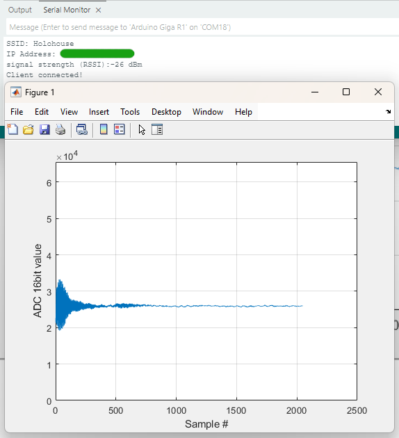
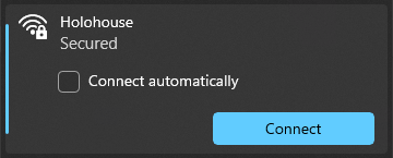
Step 13 : Connect your PC to the same WiFi network and run the script.
Results : Below is a figure showing the measurement results.
Notice that with WiFi, your Serial is freed up, allowing to use it for convenient debugging purposes on Arduino or to send data in parallel to the WiFi connection.